Understanding Construction Drawings 7th Edition Answer Key is the ultimate resource for students, professionals, and anyone seeking to master the art of interpreting architectural and engineering drawings. This comprehensive guide provides a deep dive into the conventions, symbols, and abbreviations used in construction drawings, empowering readers with the knowledge and skills necessary to navigate complex project plans with confidence.
With its clear explanations, detailed examples, and practical exercises, this book demystifies the intricacies of construction drawings, enabling readers to effectively communicate with architects, engineers, and contractors throughout the construction process. Whether you’re a novice or an experienced professional, Understanding Construction Drawings 7th Edition Answer Key is an indispensable tool that will enhance your understanding and elevate your construction projects to new heights.
Understanding Construction Drawings 7th Edition Overview
Understanding Construction Drawings, 7th Edition provides a comprehensive overview of the conventions and practices used in the creation and interpretation of construction drawings. The book is written for students in architecture, engineering, construction, and interior design, and is also a valuable resource for professionals in the construction industry.
The book is divided into six sections, each of which covers a different aspect of construction drawings. The first section introduces the basics of construction drawings, including the different types of drawings, the symbols and abbreviations used, and the conventions for dimensioning and scaling.
The second section covers architectural drawings, including floor plans, elevations, and sections. The third section covers structural drawings, including framing plans, foundation plans, and details. The fourth section covers mechanical, electrical, and plumbing (MEP) drawings, including HVAC plans, electrical plans, and plumbing plans.
The fifth section covers construction detail drawings, including shop drawings and fabrication drawings. The sixth section covers construction specifications, including the different types of specifications and the conventions for writing them.
Architectural Drawing Conventions

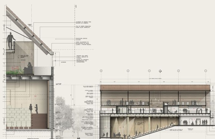
Architectural drawings are used to communicate the design of a building to the construction team. They include floor plans, elevations, sections, and details. Floor plans show the layout of a building from above, elevations show the exterior and interior of a building from the side, sections show the interior of a building from the front or back, and details show the construction of specific parts of a building.
Architectural drawings use a variety of symbols and abbreviations to represent different elements of a building. For example, a circle with a line through it represents a door, a square with a line through it represents a window, and a triangle represents a roof.
Structural Drawing Conventions, Understanding construction drawings 7th edition answer key
Structural drawings are used to communicate the design of a building’s structure to the construction team. They include framing plans, foundation plans, and details. Framing plans show the layout of a building’s structural members, foundation plans show the design of a building’s foundation, and details show the construction of specific parts of a building’s structure.
Structural drawings use a variety of symbols and abbreviations to represent different elements of a building’s structure. For example, a circle with a cross inside it represents a column, a square with a cross inside it represents a beam, and a triangle with a cross inside it represents a truss.
Mechanical, Electrical, and Plumbing (MEP) Drawing Conventions
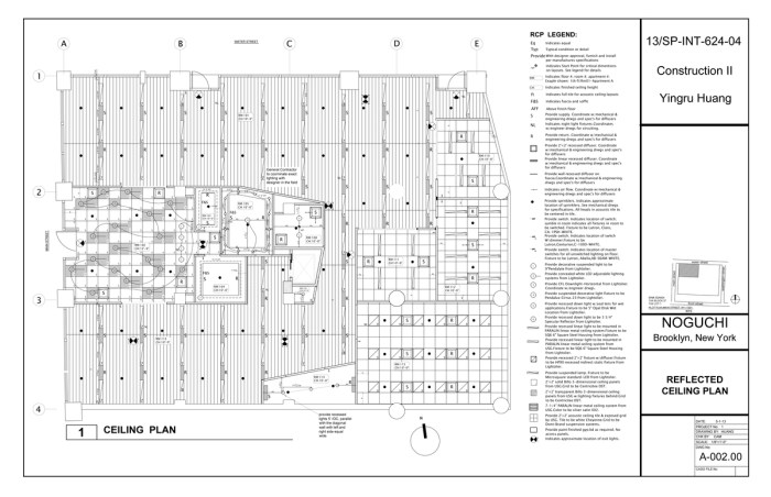
MEP drawings are used to communicate the design of a building’s mechanical, electrical, and plumbing systems to the construction team. They include HVAC plans, electrical plans, and plumbing plans. HVAC plans show the layout of a building’s heating, ventilation, and air conditioning systems, electrical plans show the layout of a building’s electrical system, and plumbing plans show the layout of a building’s plumbing system.
MEP drawings use a variety of symbols and abbreviations to represent different elements of a building’s mechanical, electrical, and plumbing systems. For example, a circle with a fan inside it represents a fan, a square with a lightning bolt inside it represents an electrical outlet, and a triangle with a faucet inside it represents a plumbing fixture.
Construction Detail Drawings
Construction detail drawings are used to communicate the design of specific parts of a building to the construction team. They include shop drawings and fabrication drawings. Shop drawings are created by the contractor and show the details of how a particular part of a building will be constructed.
Fabrication drawings are created by the manufacturer and show the details of how a particular part of a building will be fabricated.
Construction detail drawings use a variety of symbols and abbreviations to represent different elements of a building’s construction. For example, a circle with a line through it represents a bolt, a square with a line through it represents a weld, and a triangle with a line through it represents a cut.
Construction Specifications
Construction specifications are written documents that describe the materials, methods, and workmanship that will be used to construct a building. They are used to ensure that all of the parties involved in the construction process are aware of the requirements for the project.
Construction specifications are divided into sections, each of which covers a different aspect of the construction process. For example, the general conditions section covers the overall requirements for the project, the architectural section covers the requirements for the building’s structure and exterior, and the mechanical section covers the requirements for the building’s mechanical systems.
Using Construction Drawings in the Field
Construction drawings are used by the construction team to build a building. They are used to lay out the building, to install the materials, and to finish the building. It is important for the construction team to be able to read and understand construction drawings in order to build the building correctly.
There are a few things that the construction team can do to ensure that they are using construction drawings correctly. First, they should make sure that they have the most up-to-date drawings. Second, they should review the drawings carefully before starting any work.
Third, they should ask questions if they do not understand something. Finally, they should follow the drawings exactly.
FAQ Overview: Understanding Construction Drawings 7th Edition Answer Key
What is the purpose of Understanding Construction Drawings 7th Edition Answer Key?
Understanding Construction Drawings 7th Edition Answer Key provides a comprehensive guide to interpreting architectural and engineering drawings, empowering readers to effectively communicate with architects, engineers, and contractors throughout the construction process.
Who is the intended audience for this book?
Understanding Construction Drawings 7th Edition Answer Key is designed for students, professionals, and anyone seeking to master the art of interpreting architectural and engineering drawings.
What are the key features of this book?
Understanding Construction Drawings 7th Edition Answer Key features clear explanations, detailed examples, and practical exercises that demystify the intricacies of construction drawings.